Solid-State Batteries: What’s Real in 2026, What Isn’t, and How to Plan
Why this matters this week
Solid-state batteries (SSBs) moved from slideware to “pilot reality” in the last 12–18 months. For engineering leaders in EV and grid-scale systems, this isn’t a vague 2035 story anymore—it’s starting to affect roadmaps and sourcing conversations today.
Why you should care now:
- EV OEMs are signing binding offtake and JV deals around solid-state chemistries with specific dates attached (2027–2030), not “sometime next decade.”
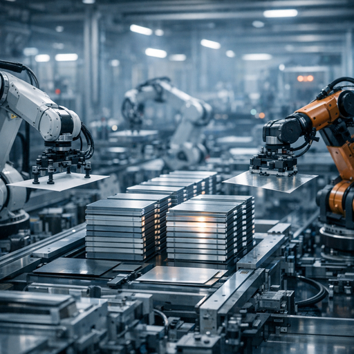
- Several major cell lines have transitioned from coin/pouch lab cells to pilot lines with >10 Ah and even >50 Ah solid-state cells, revealing actual manufacturability constraints.
- Grid storage vendors are quietly doing TCO modeling on SSB variants for high-temperature and long-duration applications where traditional lithium-ion (NMC/LFP) is painful.
You’re going to be asked:
– “Should we design our next EV platform or BMS to be ‘solid-state ready’?”
– “Is there a credible path to higher energy density pack designs in 2028–2030 that we must pre-architect for?”
– “Does this change our grid storage or microgrid strategy?”
This post focuses on mechanisms and trade-offs: where solid-state batteries are actually at, what’s blocking scale, and what technical decisions you can sensibly make in the next week.
What’s actually changed (not the press release)
Marketing language around “500 Wh/kg,” “fast charging in 10 minutes,” and “no fire risk” is years old. The real changes are more boring but more important.
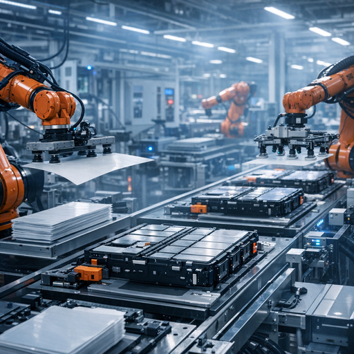
1. Cell formats and capacities are no longer toy-sized
Over the last 18 months, multiple players have:
- Moved from:
- Coin cells (10–100 mAh) and tiny pouches (<1 Ah)
- To:
- Prototype automotive-class cells in the 20–100 Ah range
- Stacked-layer designs resembling actual EV modules
This matters because:
– Scaling thickness and area exposes:
– Mechanical issues (fracturing, delamination of solid electrolyte)
– Current distribution problems (hot spots, local lithium plating)
– Yield challenges (pinholes, voids, edge defects)
We’re now seeing real cycle data at EV-relevant conditions (e.g., 1–2 C charge, realistic SOC windows, 20–45°C) rather than cherry-picked gentle cycles.
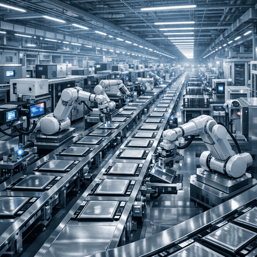
2. Manufacturing constraints are now the main bottleneck
On lab cells, solid electrolytes and lithium metal anodes already show compelling performance:
- High energy density potential (300–450+ Wh/kg at cell level is credible on paper)
- Good fast-charging performance (especially sulfide-based systems)
- Intrinsically non-flammable solid electrolyte vs. organic liquid
But the industrial reality:
- Ceramic and sulfide solid electrolytes are:
- Brittle
- Sensitive to moisture
- Hard to process at scale with tight tolerances
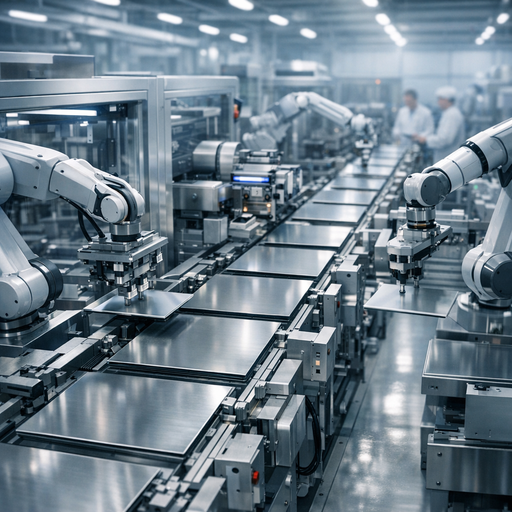
- Yield on early pilot lines is low:
- More scrap due to cracks, voids, edge pinching
- Very narrow process windows for temperature, pressure, humidity
The story shifted from “Can we build a solid-state cell that works?” to “Can we build 10 million of them per year at 95–98% yield?”
3. Timelines quietly hardened and slipped (both)
Most big timelines have done this:
- Public promise: mid-decade (2025–2027) “commercialization”
- Reality trend:
- 2025–2027: specialty, premium, or low-volume deployments
- High-end EV trims
- Motorsports / performance
- Niche aerospace or stationary
- 2028–2032: significant but not majority adoption in EVs
- 2025–2027: specialty, premium, or low-volume deployments
So “on the road in 2027” is plausible—but likely low volume and high cost, not the mainstream pack you put in a price-sensitive vehicle.
4. Pack-level implications are better understood
EV and grid teams are now modeling solid-state battery packs with real-ish assumptions:
- Higher gravimetric and volumetric energy density
- Less pack-level overhead for thermal management and safety layers
- Different thermal signatures
- Less concern about flammable electrolyte
- More concern about mechanical stress and interface degradation
- New failure modes around:
- Dendrite penetration of solid electrolyte
- Interfacial resistance growth
- Mechanical fatigue over thousands of cycles
Result: Forward-looking pack designs are evolving, but not in a way that lets you throw away all today’s safety and thermal infrastructure.
How it works (simple mental model)
You don’t need every materials detail. You do need a reliable mental model for system-level decisions.
Classic Li-ion vs. solid-state: the delta
Conventional lithium-ion (NMC/LFP, etc.):
- Liquid organic electrolyte + porous separator soaked with electrolyte
- Graphite/silicon-based anode
- Failure modes:
- Thermal runaway driven by flammable electrolyte
- Lithium plating at high C-rates
- SEI (solid electrolyte interphase) instability on graphite/silicon
Solid-state battery:
- Solid electrolyte layer (ceramic, sulfide, polymer, or hybrid)
- Often lithium metal or high-silicon content anode
- Mechanisms that change:
- Ion transport happens in crystalline / glassy / polymer solid, not liquid
- Dendrite growth constrained (in theory) by mechanical strength of electrolyte
- Flammability risk reduced (still other combustible components in pack)
Two key knobs that matter for you
-
Electrolyte type
- Sulfide-based (e.g., Li₁₀GeP₂S₁₂ variants)
- High ionic conductivity (~liquid-like)
- Sensitive to moisture (produces H₂S)
- More promising for high-power EV use if manufacturing is solved
- Oxide/ceramic (e.g., garnet LLZO)
- More chemically stable
- Mechanically strong but brittle
- Interfaces are hard to engineer (high interfacial resistance)
- Polymer / hybrid
- Lower ionic conductivity at room temperature
- Often needs elevated temperature or hybrid liquid components
- Closer to existing manufacturing methods
- Sulfide-based (e.g., Li₁₀GeP₂S₁₂ variants)
-
Anode strategy
- Full lithium metal
- Best energy density
- Toughest to manage mechanically and electrochemically
- “Anode-less” (lithium plated in-situ)
- Simple initial construction
- Sensitive to cycling conditions and current distribution
- Silicon-rich or graphite-silicon composite
- Less energy density uplift, but better understood behavior
- More compatible with existing pack/BMS thinking
- Full lithium metal
System-level mental shortcut
Think of SSBs as “Li-ion v2 with:
- More fragile mechanical stack
- Different failure modes (cracks and interfaces vs. fire)
- Potentially significantly higher energy per liter/kg
- Higher process and capex complexity in manufacturing
This is a manufacturing and reliability problem more than a “invent a new physics” problem.
Where teams get burned (failure modes + anti-patterns)
Patterns from early adopters and internal R&D groups:
1. Over-indexing on cell-level spec sheets
Anti-pattern:
– Designing system architecture around:
– “>400 Wh/kg”
– “2,000 cycles at 2C”
– “10-minute charge”
Reality:
– Those numbers often:
– Come from small-format cells under carefully chosen conditions
– Ignore pack integration losses, thermal constraints, safety margins
– Pack-level energy density bump vs. excellent current NMC/LFP packs may be:
– Realistic: +30–60%
– Not: “2x” in production-ready systems this decade
Consequence:
– Over-promised vehicle range or storage capacity
– BMS and thermal design painted into a corner trying to hit marketing specs
2. Ignoring mechanical and packaging constraints
SSB modules care a lot about:
- Stack pressure (too little → contact loss; too much → cracking)
- Dimensional stability during cycling
- Tolerance stack-ups in large-area cells
Teams burned by:
- Reusing current module designs assuming “it’s just another cell chemistry”
- Underestimating the need for uniform clamping and long-term mechanical stability
- Discovering late that packaging adds more mass/volume back than expected
3. Treating “no liquid electrolyte” as “no safety budget”
Yes, removing flammable liquid reduces fire risk. No, it doesn’t mean:
- No thermal management
- No need for containment or venting strategies
- No runaway potential (exothermic reactions can still happen at high states of abuse)
Anti-pattern:
– Slashing safety layers in pack design too early to showcase aggressive energy density, then backtracking when abuse testing reveals new failure modes.
4. Assuming drop-in BMS behavior
Common mistake:
- Assuming existing BMS strategies and algorithms transfer 1:1:
- SOC/SOH estimation models tuned for graphite-based anodes and liquid electrolytes
- Same charge profiles and derating logic
But SSBs may have:
- Non-linear interfacial resistance growth
- Different temperature and current sensitivity for degradation
- Different safe charge limits vs. SOC windows
Teams get burned when:
- They treat SSBs like a chemisty tweak instead of a fundamentally different aging/failure model.
Practical playbook (what to do in the next 7 days)
You can’t solve solid-state manufacturing in a week, but you can make your roadmap less fragile.
1. Lock your horizon: pick a realistic SSB adoption window
For most EV and grid product teams, anchor on:
- 2026–2028: Mostly pilot and niche deployments; don’t rely on SSB for volume products.
- 2028–2032: Plausible window for serious adoption in select segments for major OEMs.
Action (this week):
- Write down: “Our baseline planning assumes no SSB dependence for [product X] until [year Y].”
- Keep it conservative; treat earlier availability as upside, not a requirement.
2. Separate architecture decisions from chemistry decisions
Design system components to be chemistry-agnostic where practical:
-
For EV platforms:
- Define pack envelope, mounting, and thermal infrastructure in a way that can support:
- Today’s high-end NMC or LFP
- A future SSB pack with slightly different voltage / thermal profile
- Avoid locking in super narrow expectations on:
- Cell dimensions
- Cooling plate geometry
- Compression hardware that can’t be adjusted
- Define pack envelope, mounting, and thermal infrastructure in a way that can support:
-
For grid systems:
- Design enclosures, HVAC, and safety systems to accommodate:
- Different operating temperatures
- Moderate improvements in energy density
- Do not assume room-temp polymer SSBs;
- Design enclosures, HVAC, and safety systems to accommodate: